Approaches
The different type of IFR approaches and related information to flying them.
There are two basic kinds of approaches: Precision and Non-Precision. Precision, as the name implies, provide much more accurate navigation. Specifically, they provide more precise lateral and vertical guidance. Precision approaches prescribe a decision altitude or height where the pilot decides to either continue the approach or go missed. Non-precision, on the other hand, prescribe two things: a minimum descent altitude (or height), and a missed approach point. In a non-precision approach, you descend down to the MDA, then hold at or above that altitude until you either have everything needed to continue the approach, or you reach the missed approach point. If you reach the missed approach point, and are unable to continue the approach, you must execute the missed approach procedure.
Descending below MDA/DA
You can descend below the MDA/DA when all of the following conditions are true:
- The aircraft is continuously in a position from which a descent to a landing on the intended runway can be made at a normal rate of descent using normal maneuvers. i.e. no chop and drop/slipping.
- The flight visibility is not less than the visibility prescribed in the standard instrument approach being used.
- At least one of the following visual references for the intended runway (the runway environment) is distinctly visible and identifiable to the pilot:
- The approach light system, except that the pilot may not descend below 100 feet above the touchdown zone elevation using the approach lights as a reference unless the red terminating bars or the red side row bars are also distinctly visible and identifiable.
- The threshold.
- The threshold markings.
- The threshold lights.
- The runway end identifier lights.
- The visual glideslope indicator.
- The touchdown zone or touchdown zone markings.
- The touchdown zone lights.
- The runway or runway markings.
- The runway lights.
Approach Category
See AIM 5-4-7 (e).
The approach category for the aircraft is defined by the approach speed - VREF. Though, if you decide to fly the approach at a higher speed than VREF, then you must use the minimums specified for the category containing the speed you’re flying at (e.g. if you’re in a plane that with a VREF of 85 kts, but decide to fly the approach at 95 kts, then you must use the minimums defined for Category B).
| Category A | Category B | Category C | Category D | Category E | |
|---|---|---|---|---|---|
| Speed (kts) | 0 to 90 | 91 to 120 | 121 to 140 | 141 to 165 | 165 or greater |
Circling
See AIM 5-4-20.
Circling is a maneuver conducted after an approach, but is not a type of approach itself. Circling is performed whenever the final approach course is not aligned with the runway (within 30°), when landing on a different runway from the approach flown, or when the runway is not specified in the approach (e.g. flying a VOR-A).
Circling may be done if the winds do not favor the runway the chosen approach is for - e.g. if winds favor runway 15, but the approach is for runway 25, then you might fly the approach for runway 25, circle to land runway 15. It can also be done for other reasons - if there is VFR aircraft primarily using a different runway from the one specified for the approach you’re using, for example. Some approaches (commonly, VOR approaches) only specify circling.
Circling Minimums
Published minimums provide at least a 300 foot obstacle clearance when you remain within the appropriate area of protection. Remember to descend to the circling MDA/DA, not the straight-in MDA.
If no circling minimums are published, circling requires ATC authorization and at basic VFR (at least 1000 ft ceiling with visibility 3+ statute miles).
Remain at or above the circling MDA altitude until the aircraft is “continuously in a position from which a descent to a landing on the intended runway can be made using normal maneuvers”. This is typically just inside the 180. Abeam for most circling minimums would have you low on downwind.
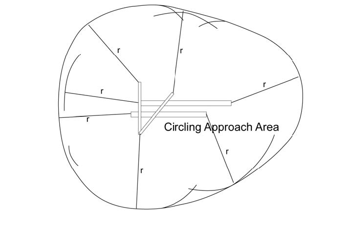
Circling Radius
Depending on the approach category (speed you fly at), you have different circling radius - the minimum distance you must remain from the runway while circling to land.
 .
.
Standard Circling Radius
Circling approach protected areas developed prior to late 2012 use the radius distances shown below.
| Circling MDA | CAT A | CAT B | CAT C | CAT D | CAT E |
|---|---|---|---|---|---|
| All altitudes | 1.3 NM | 1.5 NM | 1.7 NM | 2.3 NM | 4.5 NM |
Expanded Circling Radius
Per the AIM, Circling approach protected areas developed after late 2012 use the radius distance shown below.
| Circling MDA (feet MSL) | CAT A | CAT B | CAT C | CAT D | CAT E |
|---|---|---|---|---|---|
| 1000 or less | 1.3 NM | 1.7 NM | 2.7 NM | 3.6 NM | 4.5 NM |
| 1001 to 3000 | 1.3 NM | 1.8 NM | 2.8 NM | 3.7 NM | 4.6 NM |
| 3001 to 5000 | 1.3 NM | 1.8 NM | 2.9 NM | 3.8 NM | 4.8 NM |
| 5001 to 7000 | 1.3 NM | 1.9 NM | 3.0 NM | 4.0 NM | 5.0 NM |
| 7001 to 9000 | 1.4 NM | 2.0 NM | 3.2 NM | 4.2 NM | 5.3 NM |
| 9001 and above | 1.4 NM | 2.1 NM | 3.3 NM | 4.4 NM | 5.5 NM |
Missed Approaches
Most instrument approach procedures also have a missed procedure. These are described in the top-left box of the approach plate, and then visually depicted as part of the top-down view.
If you choose to, must, or are instructed to go missed, you follow those instructions. If you were not on the final approach course (that is, if you were circling to land), then you get back on the final approach course as part of going missed.
See this article from AOPA on going missed.
See this article from BoldMethod on going missed below the MDA/DA
PT - Procedure Turn
Depicted as a line with a barb from a course in an approach plate. The barb indicates the direction to turn. Procedure turns are maneuvers enable the following:
- course reversal
- descent from an IAF
- Inbound course interception.
Procedure turns or hold-in-lieu-of-PTs are mandatory whenever they are depicted on the approach plate. However, they are not permitted when:
- “NoPT” is depicted on the plate
- Radar vectors to final
- Conducting a timed approach from a holding fix.
The maximum speed when performing a procedure turn is 200 kts IAS. You must remain within the charted distance (usually 10 NM), and comply with published altitudes for obstacle clearance.
The shape of the maneuver is mandatory if a teardrop or hold-in-lieu-of-PT is published. Otherwise, only the direction.
A teardrop procedure may be be published instead of a procedure turn.
Do not perform a procedure turn when SHARPTT:
- Straight-in approach clearance
- Holding in lieu of a procedure turn
- DME Arc
- Radar vectors to final
- NoPT shown on chart
- Timed approach from a holding fix
- Teardrop course reversal.
ILS - Instrument Landing System
the ILS is composed of two main parts: the localizer and the glide slope. In addition, there are marker beacons at specific locations.
The ILS is described mostly in AIM 1-1-9.
Localizer
The localizer is essentially a more-sensitive VOR that broadcasts a single radial. It’s located inline with the runway, behind the runway. It broadcasts 2 signals - one at 90 Hz, the other at 150 Hz. The intersection of the signals is aligned with the extended runway centerline, and the receiver on the airplane can interpret these to show how off course the airplane is.

The width of it is between 3° and 6° - such that the width at the runway threshold is 700 feet. Usually, it’s a 5° total width (2.5° full deflection on each side, or 4 times more sensitive than a VOR). The coverage range is a 35° on each side of the centerline up to 10 NM. After that, out to 18 NM, with 10° each side of the centerline. It goes out to an altitude of 4500 feet.

Glide Slope
The glide slope provides vertical course guidance. The transmitter is located off to the side of the runway (about 250-650 away from the runway centerline), between 750 and 1,250 feet behind the runway threshold.
Similar to the localizer, the glide slope broadcasts 2 signals, at 90 and 150 Hz, with the intersection of them providing a - usually - 3° glide slope down to the runway.
A glide slope has a width of 1.4° (0.7° on either side), with a range out to 10 NM. As previously stated, it provides a 3° slope, unless otherwise charted.
⚠️ Due to, literally how physics works, there’s a false glide slope significantly above the normal glide slope.

Marker Beacons
Marker beacons provide range information over specific points on the approach. There are 3 that are part of an ILS, named the outer marker, middle marker, and inner marker. There also exists the back course marker, but that’s not part of the ILS approach.
| Marker Type | Location | Color | Signal |
|---|---|---|---|
| Outer Marker | 4-7 NM out. Approximately where the aircraft should intercept the glide slope. | Blue | Dashes “- - -” |
| Middle Marker | ~3500 feet from the runway & 200 feet above the touchdown zone elevation. Where the glide slope meets the decision height. | Amber | “· - · -” |
| Inner Marker | Between the middle marker and the runway threshold. Indicates where the glide slope meets the decision height on a CAT II ILS approach. | White | All dots. “· · · ·” |
| Back Course | The final approach fix on “selected back course approaches”, not a part of the ILS approach. | White | two-dots “·· ··” |
ALS - Approach Light Systems
See AIM 2-1-1.
- Provides basic visible means to transition between instrument-guided flight into a visual approach.
- The ALS extends from the landing threshold into the approach area up to:
- 2,400 to 3,000 feet for precision instrument runways, and
- 1,400 to 1,500 feet for non-precision instrument runways.
- May include sequenced flashing lights, which appear to the pilot as a ball of light traveling towards the runway at 2 times a second.
- The visible parts of the ALS configuration can help the pilot estimate flight visibility.
ILS Minimums
See this chart:
| Category | Visibility | Decision Height |
|---|---|---|
| CAT I | 2,400 feet or 1,800 feet | 200 feet |
| CAT II | 1,200 feet | 100 feet |
| CAT IIIa | > 700 feet | < 100 feet or no decision height |
| CAT IIIb | 150 to 700 feet | < 50 feet or no decision height |
| CAT IIIc | 0 feet | No decision height |
VOR Approaches
VOR approaches are useful for when there’s basically no other approach type available. They are non-precision approaches, which means they provide lateral guidance only.
Per AIM 1-2-3 (c), while you can fly the final approach segment for a VOR approach that does not specify “or GPS” using GPS, you must be monitoring the VOR on another radio. For avionics like the G1000 where you don’t have two deflecting needles, this means that you must switch the HSI from GPS to VLOC for the final approach segment.
For example, on the Corvallis VOR-A approach, you can use the GPS outbound from CVO, all the way through the procedure turn, until you turn onto the CVO R-252 course inbound. Once you turn onto the CVO R-252 inbound course (which this defines as the final approach segment), you then switch over to using the VOR to navigate.
In another example, on the Corvallis VOR RWY-17 approach, you are welcome to use the GPS through the entire DME arc, up until you turn onto the CVO R-177 course inbound.
This same concept applies also to ILS and other ground-based-navigation approaches.
DME Arcs
DME Arcs are arcing paths flown at a certain distance (measured using DME - hence the name), from a VOR. They provide a way to transfer to another radial on the VOR without using GPS or radar vectors. They’re mostly used as parts of approaches, but can be specified elsewhere.
To fly one, first start turning onto the arc when you are groundspeed * 0.01 nm from the arc (e.g. groundspeed == 100 nm/hr, then start turn when you are 1 nm from the arc). Then, follow the “twist 10, turn 10” pneumonic - for every degrees you turn, twist the desired course 10 degrees in the direction of the arc. Repeat until you reach the desired radial.
In the example of the KCVO VOR RWY-17 approach, if you are approach MAGOT from SHEDD, you are approaching the CVO R-031 radial from the south. Once you are 1 nm from that waypoint, you’ll start your turn: Switch the CDI to show the CVO R-031, and twist it 10° left (counterclockwise, in this case), to 031. Once this is done, start the turn. Be sure to also be monitoring your DME to ensure you’re maintaining 16 nm from CVO. When the needle centers, twist give it another 10° counterclockwise twist. Repeat until your next twist would take you past the CVO R-357, at which point you simply set it to R-357. As you approach that radial, start your inbound turn. Be cognizant of the reversal of the VOR (unless your avionics has reverse sensing!) until you get around to resetting your CDI to 177°, which you should do as soon as you are on the final approach course.
Note that as per above, you can also fly this arc using the GPS indicator, as the DME arc is not part of the final approach segment.
RNAV Approaches
LPV means “Localizer Performance with Vertical Guidance”, and it is not a precision approach (it’s an “Approach with Vertical Guidance (APV)”, along with BARO-VNAV, LNAV/VNAV and other types that are not required to meet precision approach standards, but do provide course and glidepath deviation.
Last updated: 2022-02-15 12:28:43 -0800